HEAT AND COOLING - PROF SPRAWLSINTRODUCTION AND OVERVIEW |
|
|
To produce
x-radiation, relatively large amounts of electrical energy must be
transferred to the x-ray tube. Only a small fraction (typically less than
1%) of the energy deposited in the x-ray tube is converted into x-rays;
most appears in the form of heat. This places a limitation on the use of
x-ray apparatus. If excessive heat is produced in the x-ray tube, the
temperature will rise above critical values, and the tube can be damaged.
This damage can be in the form of a melted anode or a ruptured tube
housing. In order to prevent this damage, the x-ray equipment operator
must be aware of the quantity of heat produced and its relationship to the
heat capacity of the x-ray tube.
The heat produced during
x-ray production can be a limiting factor:
One of the major challenges
in developing x-ray tubes for modern, high performance, CT systems is to
provide design features to accommodate the high levels of heat produced.
The figure
below identifies the factors that affect both heat production and
heat capacity.
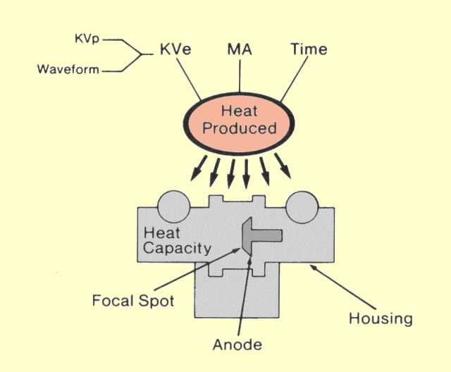 Factors That Determine the Amount of Heat Produced and the Three Areas of an X-Ray Tube That Have Specific Heat Capacities |
|
HEAT PRODUCTION |
|
|
Heat is produced
in the focal spot area by the bombarding electrons from the cathode.
Since only a small fraction of the electronic energy is converted in
x-radiation, it can be ignored in heat calculations. We will assume all
of the electron energy is converted into heat. In a single exposure, the
quantity of heat produced in the focal spot area is given by
or
In this relationship,
w is the waveform factor; its value is determined by the
waveform of the voltage applied to the x-ray tube. Values for most
waveforms encountered in diagnostic x-ray machines are: constant
potential, 1.0; three-phase, 12 pulse, 0.99; three-phase, 6-pulse, 0.96;
single-phase, 0.71.
Although the joule is the basic unit for energy and heat, it is not always used to express x-ray tube heat. The
special heat unit (HU) was introduced when single-phase equipment
was common to make it easy to calculate heat.
The relationship between a quantity of heat expressed in heat units and in joules is given by
Since the product
of the joules-to-heat unit conversion factor (1.4) and the waveform
factor for single-phase (0.71 ) is equal to 1, the following
relationship is obtained:
Here it is seen that for single-phase operation, the heat produced in heat units is the product of the
KVp and
MAS. In fact, this is why the heat unit is used. In the earlier days of
radiology, when most equipment was single-phase, it was desirable to
calculate heat quantities without having to use a waveform factor. This
was achieved by introducing a new unit, the heat unit. For three-phase,
six-pulse equipment, the heat in heat units is given by
The factor of 1.35 is the ratio of the waveform factors, 0.96/0.71.
The rate at which heat is produced in a tube is equivalent to the electrical power and is given by
The total heat delivered during an exposure, in joules or watt-seconds, is the product of the power and the exposure time
|
|
HEAT CAPACITY |
|
|
In order to evaluate the problem of x-ray
tube heating, it is necessary to understand the relationship of three
physical quantities: (1) heat, (2) temperature, and (3) heat capacity.
Heat is a form of energy and can be expressed in any energy units. In
x-ray equipment, heat is usually expressed in joules (watt-seconds) or
heat units.
Temperature is
the physical quantity associated with an object that indicates its
relative heat content. Temperature is specified in units of degrees.
Physical changes, such as melting, boiling, and evaporation, are
directly related to an object's temperature rather than its heat
content.
For a given object, the relationship between temperature and heat content involves a third quantity,
heat capacity, which is a characteristic of the object. The general relationship can be expressed as follows:
The heat capacity
of an object is more or less proportional to its size, or mass, and a
characteristic of the material known as the
specific heat. As heat is added to an object, the temperature
increases in proportion to the amount of heat added. When a given
amount of heat is added, the temperature increase is inversely
proportional to the object's heat capacity. In an object with a large
heat capacity, the temperature rise is smaller than in one with a small
heat capacity. In other words, the temperature of an object is
determined by the relationship between its heat content and its heat
capacity. This is illustrated
below.
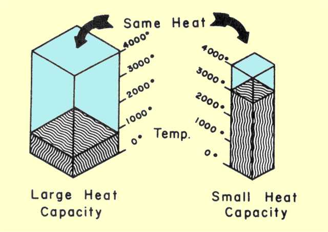 Relationship Among Heat, Temperature, and Heat Capacity
In x-ray tube operation, the goal is never to exceed specific
critical temperatures that
produce damage. This is achieved by keeping the heat content below
specified critical values related to the tube's heat capacity.
In most x-ray tubes
there are three distinct areas with critical heat capacities, as shown
below. The area with the smallest capacity is the focal spot area,
or track, and is the point at which heat is produced within the tube.
From this area, the heat moves by conduction throughout the anode body
and by radiation to the tube housing; heat is also transferred, by
radiation, from the anode body to the tube housing. Heat is removed from
the tube housing by transfer to the surrounding atmosphere. When the
tube is in operation, heat generally flows into and out of the three
areas shown. Damage can occur if the heat content of any area exceeds
its maximum heat capacity.
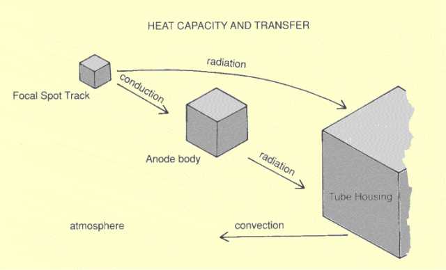 The Three Critical Heat Capacities in an X-Ray Tube |
|
FOCAL SPOT AREA |
|
|
The maximum heat capacity of the focal spot area, or track, is the major
limiting factor with single exposures. If the quantity of heat delivered
during an individual exposure exceeds the track capacity, the anode
surface can melt, as shown below.
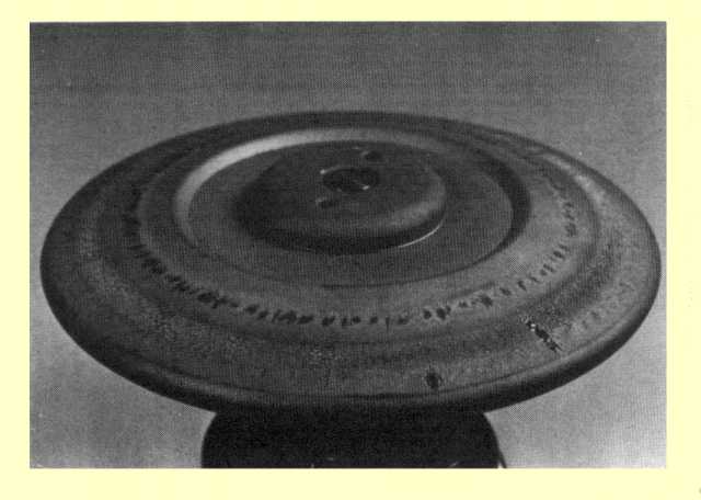 A Rotating Anode Damaged by Overheating
The capacity of a given
focal spot track is generally specified by the manufacturer in the form of
a graph, as shown below. The curves on the graph show the maximum power
(KV and MA) that can be delivered to the tube for a given exposure time
without producing overload. Graphs of this type are generally designated
tube rating charts. From this graph, it is seen that the safe power limit
of a tube is inversely related to the exposure time. This is not
surprising, since the total heat developed during an exposure is the
product of power and exposure time. It is not only the total amount of
heat delivered to the tube that is crucial, but also the time in which it
is delivered.
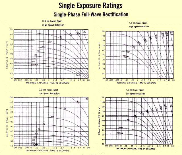 Rating Charts for an X-Ray Tube Operated under Different Conditions (Focal Spot Size, Rotation Speed, and KV Waveform)
X-ray tubes are often given single
power ratings (in kilowatts, kW). By general agreement, an
exposure time of 0.1 second is used for specifying a tube's power
rating. Although this does not describe a tube's limitations at other
exposure times, it does provide a means of comparing tubes and operating
conditions.
The significance of a power
rating is that it specifies the maximum rate (how fast) energy can safely
be applied to a tube. This can limit how short exposure times can be
made to reduce motion blurring because a short exposure time requires a
higher power (increased MA) to produce the necessary exposure.
A number of
different factors determine the heat capacity of the focal spot track.
The focal spot track is the surface area of the anode that is bombarded
by the electron beam. In stationary anode tubes, it is a small area with
dimensions of a few millimeters. In the rotating anode tube, the
focal spot track is much larger because of the movement of the anode with respect to the electron beam.
The figure below shows a small section of a rotating anode.
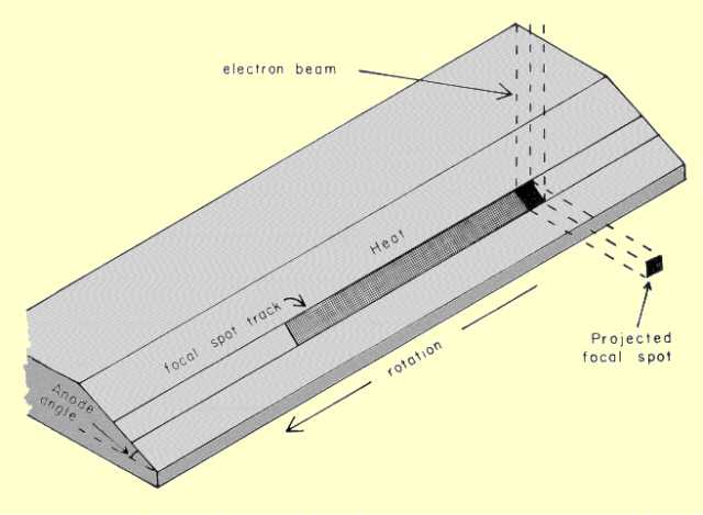 Section of a Rotating Anode Showing Relationship of Focal Spot Track to Electron Beam and Anode Angle |
|
Focal Spot Size |
|
|
From the standpoint of producing x-ray images with minimum blur, a
small focal spot is desired. However, a small focal spot tends to
concentrate heat and give the focal spot track a lower heat capacity.
The only advantage of a larger focal spot is increased heat capacity.
Many x-ray tubes have two focal spot sizes that can be selected by the
operator. The small focal spot is generally used at relatively low power
(KV and MA) settings. The large focal spot is used when the machine
must be operated at power levels that exceed the rated capacity of the
small focal spot. The specified size of an x-ray tube focal spot is the
dimensions of the effective or projected focal spot shown
in the figure above. Notice that the actual focal spot, the area
bombarded by the electron beam, is always larger than the projected, or
effective, focal spot. For a given anode angle, the width of the focal
spot track is directly proportional to the size of the projected spot.
The relationship between heat capacity and specified focal spot size is
somewhat different. In many tubes, doubling the focal spot size
increases the power rating by a factor of about 3.
|
|
Anode Angle |
|
|
The actual
relationship between focal spot width (and heat capacity) and the size
of the projected focal spot is determined by the anode angle. Anode
angles generally range from about 7° to 20°. For a given effective focal
spot size, the track width and heat capacity are inversely related to
anode angle. Although anodes with small angles give maximum heat
capacity, they have specific limitations with respect to the area that
can be covered by the x-ray beam. X-ray intensity usually drops off
significantly toward the anode end because of the
heel effect. In tubes with small angles, this is more pronounced and limits the size of the useful beam.
The figure below shows the nominal field coverage for different anode angles.
When specifying an x-ray tube for purchase, the anode angle should be selected by a compromise between heat capacity,
especially for smaller focal spots, and field of coverage.
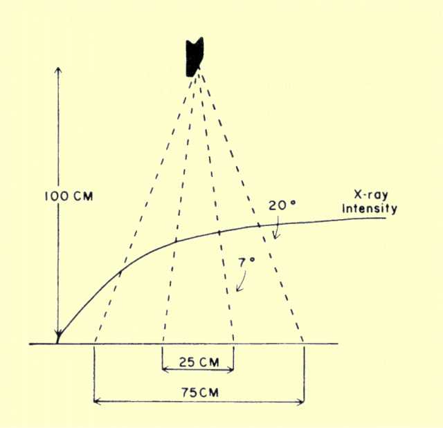 Variation of X-Ray Intensity and Maximum X-ray Beam Size Because of the Anode Heel Effect |
|
Anode Rotation Speed |
|
|
In rotating
tubes, the anode assembly is mounted on bearings and actually forms the
rotor of an electric motor. The x-ray tube is surrounded by a set of
coils that form the stator of the motor. When the coils are energized
from the power line, the rotor spins. The speed of rotation is
determined by the frequency of the applied current. When the stator
coils are operated from the 60-Hz power line, the speed of rotation is
approximately 3,000 rpm. By using a power supply that produces 180-Hz
current, rotation speeds of approximately 10,000 rpm can be obtained.
This is commonly referred to as
high-speed rotation.
The effective
length of the focal spot track is proportional to the speed of rotation
for a given exposure time. High-speed rotation simply
spreads the heat over a longer track, especially in short exposure
times. High-speed rotation generally increases the power capacity of a
tube by approximately 60%.
|
|
KV Waveform |
||||||||||||||
|
Another factor that affects the heat capacity of the focal spot track is the waveform of the
KV. Single-phase power delivers energy to the anode in pulses, as shown
below. Three-phase and constant potential generators deliver the heat at an essentially constant rate, as indicated.
The figure below compares the temperatures produced by a single-phase and a constant potential machine delivering
the same total heat. Because of the pulsating nature of
single-phase power, some points on the anode surface are raised to
higher temperatures than others. These hot spots exceed the temperature
produced by an equal amount of three-phase energy. When an x-ray tube is
operated from a single-phase power supply, the maximum power must be
less than for constant potential operation to keep the hot spots from
exceeding the critical temperature. In other words,
constant potential operation increases the effective focal spot track heat capacity and rating of an x-ray tube.
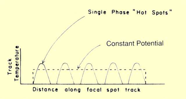 Approximate Distribution of Temperature along the Focal Spot Track for Single-Phase and Three-Phase Operation
The effect of
KV waveform on tube rating should not be confused with the effect
of waveform on heat production, which was discussed earlier. However,
both factors should be considered to determine if there is any
advantage, from the standpoint of tube heating, to using three-phase or
constant potential power. In comparing three-phase or constant potential
and single-phase operation, three factors should be considered:
The real
advantage of constant potential operation is related to the first two
factors. Because of the increased efficiency of x-ray production, and
the increased penetrating ability of the radiation, a lower
KV or MAS value is required to produce a given film exposure. This
more than compensates for the increased heat production associated with
constant potential operation. The increased rating, or maximum
permissible power, associated with the constant potential waveform also
adds to the advantage. An x-ray tube can generally be operated at a
higher power level when the power is supplied from a three-phase or
constant potential power supply, and it will also produce radiation more
efficiently.
A rating chart for an x-ray tube operated at different waveforms and rotation speeds is shown in
the figure titled, Rating Curves for an X-Ray Tube Operated under
Different Conditions. The highest power capacity is obtained
by using three-phase power and high-speed rotation; notice that the real
advantage occurs at relatively short exposure times. As exposure time
is increased, overlapping of the focal spot track and the diffusion of
heat make the difference in power capacity much less significant.
The actual rating
charts supplied by an x-ray tube manufacturer are shown in
the figure referred to in the previous paragraph. It is common
practice for each of the four operating conditions (wave-form and speed)
to be on a separate chart. Each chart contains a number of different
curves, each representing a different MA value. The vertical scale on
such a rating chart is
KV. A chart of this type is still a power rating chart. Each
combination of
KV and MA represents a constant power value. Such a chart is
easier to use, since it is not necessary to calculate the power. The
rating chart is used by the operator to determine if the technical
factors,
KV, MA, and exposure time, for a given exposure will exceed the
tube's rated capacity.
Most rotating
anode tubes contain two focal spots. As mentioned previously, the size
of the focal spot significantly affects the heat capacity. Remember that
a given x-ray tube has a number of different rating values, depending
on focal spot size, rotation speed, and waveforms. Some typical values
are shown in
the table below.
Heat Rating (in Joules) for Typical X-Ray Tube
for Exposure Time of 0.1 sec and Focal Spot Sizes of 0.7 mm and 1.5 mm
| ||||||||||||||
ANODE BODY |
|
|
The heat capacity of the focal spot track is generally the
limiting factor for single exposures. In a series of radiographic
exposures, CT scanning, or fluoroscopy, the build-up of heat in the
anode can become significant. Excessive anode temperature can crack or
warp the anode disc. The heat capacity of an anode is generally
described graphically, as shown
below. This set of curves, describing the thermal characteristics
of an anode, conveys several important pieces of information. The
maximum heat capacity is indicated on the heat scale. The heating curves
indicate the build-up of heat within the anode for various energy input
rates. These curves apply primarily to the continuous operation of a
tube, such as in CT or fluoroscopy. For a given x-ray tube, there is a
critical input rate that can cause the rated heat capacity to be
exceeded after a period of time. This is generally indicated on the
graph. If the heat input rate is less than this critical value, normal
cooling prevents the total heat content from reaching the rated
capacity.
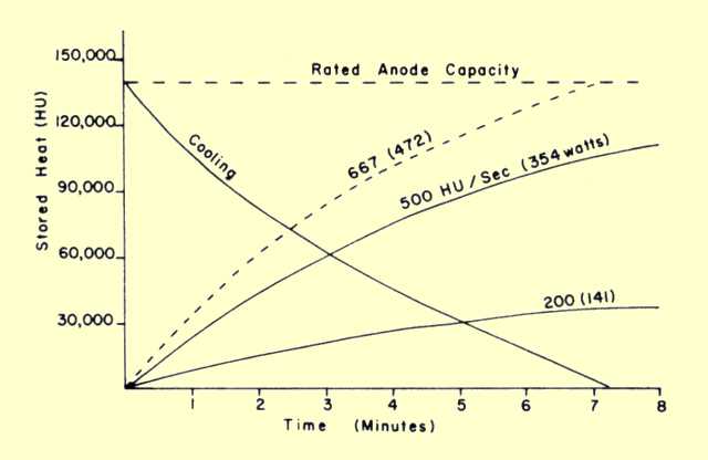 Anode Heating and Cooling Curves
The cooling curve
can be used to estimate the cooling time necessary between sets of
exposures. Suppose a rapid sequence of exposures has produced a heat
input of 90,000 HU. This is well over 50% of the anode storage capacity.
Before a similar sequence of exposures can be made, the anode must cool
to a level at which the added heat will not exceed the maximum
capacity. For example, after an initial heat input of 90,000 HU, a
cooling time of approximately 3.5 minutes will decrease the heat content
to 30,000 HU. At this point, another set of exposures producing 90,000
HU could be taken.
The cooling
rate is not constant. An anode cools faster when it has a high heat
content and a high temperature. In CT scanning, when anode heating is a
limiting factor, a higher scan rate can be obtained by operating the anode
with the highest safe heat content since the cooling rate is higher for a
hot anode and more scans can be obtained in a specific time than with a
cool anode.
Most
CT systems have a display that shows the anode heat content as a
percentage of the rated capacity during and after a scan.
The anodes in
most radiographic equipment are cooled by the natural radiation of heat
to the surrounding tube enclosures. However, anodes in some high powered
equipment, such as that used in CT, are cooled by the circulation of
oil through the anode to a heat exchanger (radiator).
Anode damage can
occur if a high-powered exposure is produced on a cold anode. It is
generally recommended that tubes be warmed up by a series of low energy
exposures to prevent this type of damage.
|
|
TUBE HOUSING |
|
|
The
third heat capacity that must be considered is that of the tube
housing. Excessive heat in the housing can rupture the oil seals, or
plugs. Like the anode, the housing capacity places a limitation on the
extended use of the x-ray tube, rather than on individual exposures.
Since the housing is generally cooled by the movement of air, or
convection, its effective capacity can be increased by using forced air
circulation.
The housing heat
capacity is much larger than that of the anode and is typically over 1
million HU. The time required for a housing to dissipate a given
quantity of heat can be determined with cooling charts supplied by the
manufacturer.
|
|
CLINICAL APPLICATIONS |
|
|
The heat characteristics of x-ray tubes should be considered when tubes are selected
and specified for specific clinical applications and should be used as a guide to proper tube operation.
It is often the heat in the
focal spot that limits the use of small focal spots that are desirable for
good image detail.
The rapid accumulation of
heat (because of high power operation) in the anode can be a limiting
factor in CT. It depends on the design characteristics of the tube.
Many x-ray systems,
including CT, have built-in safety features that will not allow the
equipment to be operated in an "overheated" condition.
| |

No comments:
Post a Comment