|
|||||
|
|
|||||
INTRODUCTION AND OVERVIEW |
|||||
|
When an x-ray beam enters a patient's body, a large portion of the
photons engage in Compton interactions and produce scattered radiation.
Some of this scattered radiation leaves the body in the same general
direction as the primary beam and exposes the image receptor. This
scattered radiation reduces image contrast. The degree of
contrast loss depends on the scatter content of the radiation
emerging from the patient's body. In most radiographic and fluoroscopic
procedures, the major portion of the x-ray beam leaving the patient's
body is scattered radiation. This, in turn, significantly reduces
contrast.
Contrast reaching an x-ray image receptor was previously described as the
difference in exposure to the object area within an image expressed as a
percentage of the exposure to the surrounding background. Maximum
contrast, i.e., 100%, is obtained when the object area receives no
exposure with respect to the background. A previous chapter, X-ray
Image Formation and Contrast, discussed the reduction of
contrast because of x-ray penetration through the objects in the body
being imaged. This chapter describes the further reduction of contrast by scattered radiation.
|
|||||

CONTRAST REDUCTION |
|
|
The basic concept of contrast reduction by scattered radiation is illustrated
below. For simplicity, it is assumed that the object within the body shown
here is not penetrated and, if it were not for scattered radiation, would
produce 100% contrast.
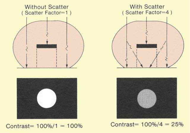 Reduction of Image Contrast by Scattered Radiation
The object is assumed to be embedded in a larger mass of material,
such as the human body, that produces the scattered radiation. The
exposure to the background area of the receptor, or film,
(shown here as the black area) is produced by radiation that
penetrates the body adjacent to the object plus the scattered radiation.
For a given x-ray machine setting, the background area exposure is
proportional to PS, the product of the penetration through the patient
(P) and the scatter factor (S). For the same exposure conditions,
the exposure to the object area,
that is in the shadow of the object, is proportional to P (S
- 1 ). By combining these expressions for relative background and
object area exposure, it can be shown that the contrast
with scatter (Cs) is inversely related to the value of the scatter factor, as follows:
Cs (%) = 100/S. This relationship shows that as the proportion of scattered radiation in the x-ray beam increases, contrast proportionally decreases. For example, if the scatter factor has a value of 4, the contrast between the object and background areas will be reduced to 25%. In other words, the object area exposure is 75% of the exposure reaching the surrounding background. The contrast can also be determined as follows. The ratio of scattered to primary radiation is always S - 1. For a scatter factor value of 4, the scatter-primary ratio is 3. The background area exposure is, therefore, composed of one unit of primary and three units of scattered radiation. The object area receives only the three units of scattered radiation. This yields an object area exposure of 75% of background and a contrast of 25%.
With respect to image contrast, the scatter factor, S, is also the contrast reduction factor.
For example, if the scatter (contrast reduction) factor has a value of
2, the resulting contrast will be 50%. This is a reduction of 100%
contrast by a factor of 2. A scatter factor value of 5 reduces contrast
by a factor of 5, or down to 20%.
The figure below shows the general relationship between contrast
and scatter factor. The value of the scatter factor is primarily a
function of patient thickness, field size, and
x-ray beam spectrum as determined by the KV. In examinations of
relatively thick body sections, contrast reduction factors of 5 or 6 are
common.
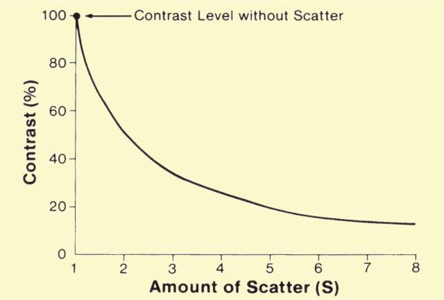 Relationship between Contrast Reduction and Amount of Scatter
We developed our discussion of contrast reduction using an
non-penetrated object
(like a piece of metal) that would produce 100% contrast in the
absence of scatter. Most objects within the body are penetrated to some
extent. Therefore, contrast is reduced by both object penetration and
scattered radiation. For example, if an object is 60% penetrated (40%
contrast), and the scatter factor, S, has a value of 4, the final
contrast will be 10%.
Since scattered radiation robs an x-ray image of most of its contrast, specific actions must be taken to regain some of the lost contrast. Several methods can be used to reduce the effect of scattered radiation but none is capable of restoring the full image contrast. The use of each scatter reduction method usually involves compromises, as we will see below. |
|
COLLIMATION |
|
|
The amount of scattered radiation is generally proportional to the
total mass of tissue contained within the primary x-ray beam. This is,
in turn, determined by the thickness of the patient and the area or
field size being exposed. Increasing the field size increases the total
amount of scattered radiation and the value of the scatter
contrast-reduction factors. Therefore, one method of reducing scattered
radiation and increasing contrast is to reduce the field size with x-ray
beam collimators, cones, or other beam-limiting devices, as illustrated
below. This method is limited by the necessity to cover a specific
anatomical region. However, in most situations, contrast can be
improved by reducing the field size to the smallest practical value.
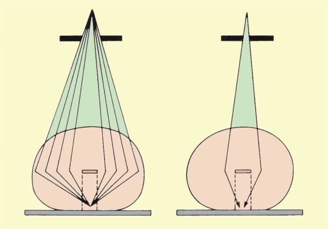 Contrast Improvement by Reducing X-Ray Beam Size |
|
AIR GAP |
|
|
The quantity of scattered radiation in an x-ray beam reaching a
receptor can be reduced by separating the patient's body and receptor
surface, as shown
below. This separation is known as an air gap. Scattered
radiation leaving a patient's body is more divergent than the primary
x-ray beam. Therefore, scattered radiation spreads out of the primary
beam area. The
reduction of scattered radiation in proportion to primary
radiation increases with air-gap distance. Several factors must be
considered when using this method of scatter reduction. Patient exposure
is increased because of the inverse-square effect. The use of an air
gap introduces magnification. Therefore, a larger receptor size is
required to obtain the same patient area coverage. If the air gap is
obtained by increasing the tube-to-receptor distance, the x-ray
equipment must be operated at a higher output to obtain adequate
receptor exposure.
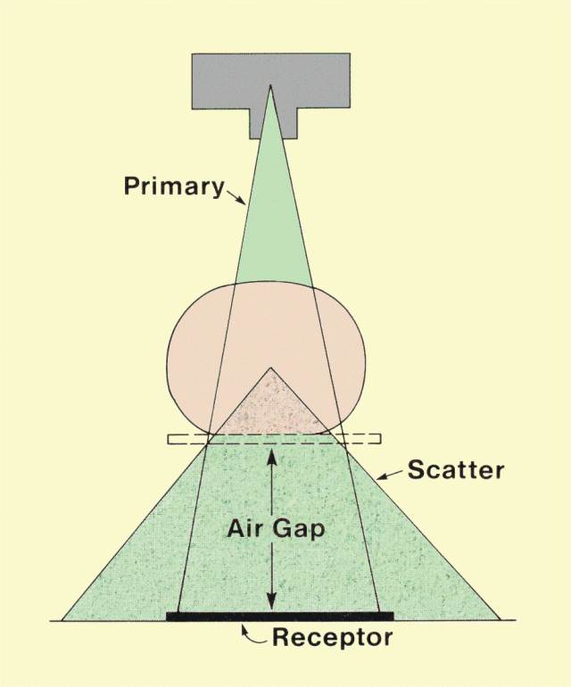 Contrast Improvement by Using an Air Gap
Also, increasing the separation distance between the patient and
the receptor increases focal spot blurring. It is usually necessary to
use relatively small focal spots with an air-gap technique.
One
common use of the air gap is in magnification mammography. Since an
air gap is produced by separating the breast from the receptor to produce
magnification, it can be used for scatter reduction. The usual
procedure is to remove the grid and rely on the air gap in magnification
mammography.
|
|
GRIDS |
|
|
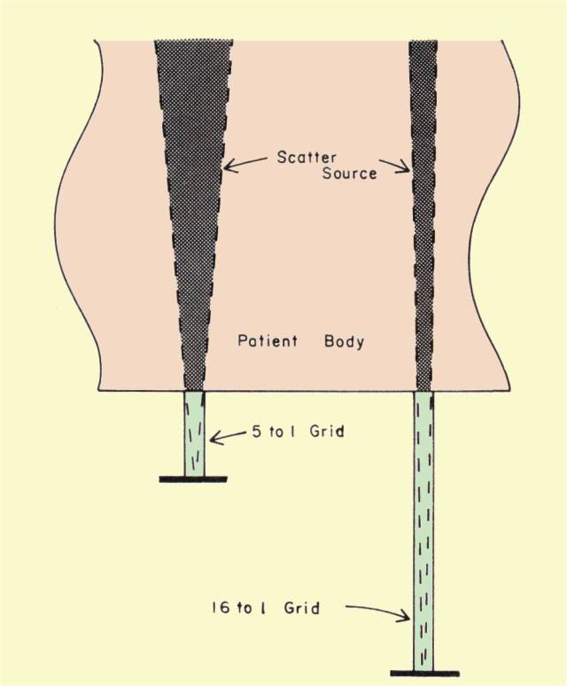
In most examinations, the most effective and practical method of
removing a portion of the scattered radiation is to use a grid. The grid
is placed between the patient's body and the receptor, as shown
below. It is constructed of alternate strips of an x-ray-absorbing
material, such as lead, and a relatively non-absorbing interspace
material, such as fiber, carbon, or aluminum. Under normal operating
conditions, the grid strips are aligned with the direction of the
primary x-ray beam. In most grids, the interspaces are angled so as to
align with a specific point in space. These are designated focused
grids. The
focal point of the grid should coincide with the focal spot of the x-ray tube,
which is the source of the primary radiation. In an unfocused grid, the
interspaces and strips are parallel and are not aligned with a single
point in space. Because the x-ray beam direction is aligned with the
grid, much of the primary radiation passes through the interspaces
without encountering the lead strips. Scattered radiation, on the other
hand, leaves the patient's body in a direction different from that of
the primary beam, as shown in
the second figure below. Since scattered radiation is not
generally lined up with the grid strips, a large portion of it is
absorbed by the grid. The ideal grid would absorb all scattered
radiation and allow all primary x-rays to penetrate to the receptor.
Unfortunately, there is no ideal grid, because all such devices absorb
some primary radiation and allow some scattered radiation to pass
through.
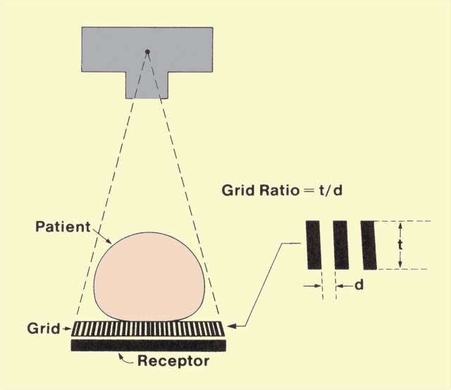 The General Design of a Grid 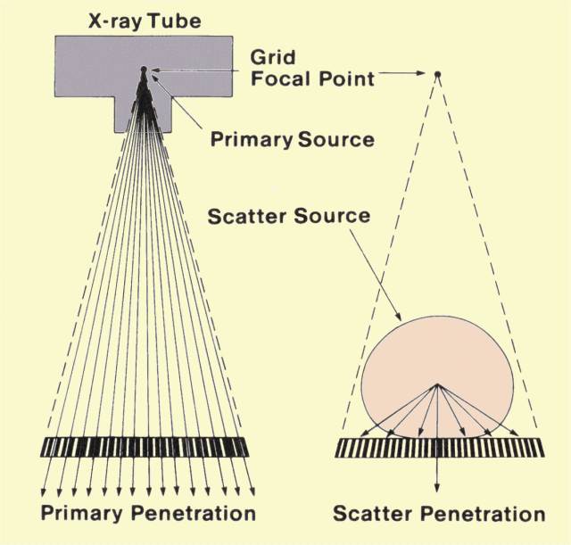 Selective Absorption of Scattered Radiation by a Grid
The penetration characteristics for scattered radiation are
largely determined by the dimensions of the lead strips and the
interspaces. The significant dimensions are illustrated in
the top figure above. The height of the strips, t, is the
thickness of the grid and is typically in the range of 2 mm to 5 mm.
Another significant dimension is the width of the interspace, d. This
dimension varies with grid design, but generally ranges from 0.25 mm to
0.4 mm. With respect to grid performance, the important variable is the
ratio of these two dimensions, which is designated the grid ratio. Most
grids have ratios ranging from 5:1 to 16:1. The selection of the
appropriate grid ratio for a given examination involves the
consideration of a number of factors. Although grids with higher ratios
eliminate more scattered radiation, they tend to increase patient
exposure and x-ray tube loading and require more precise positioning.
|
|
GRID PENETRATION |
|
|
A
knowledge of the total penetration of primary and scattered radiation
through a grid is necessary to select appropriate exposure factors for
the x-ray machine.
The total grid penetration is a function of scattered-radiation
penetration and penetration of primary radiation. The relationship also
involves the proportion of scattered radiation in the beam, S.
The figure below shows the general relationship between the two
components (primary radiation and scatter) of grid penetration and grid
ratio. In general, the penetration of both types of radiation decreases
as the grid ratio is increased.
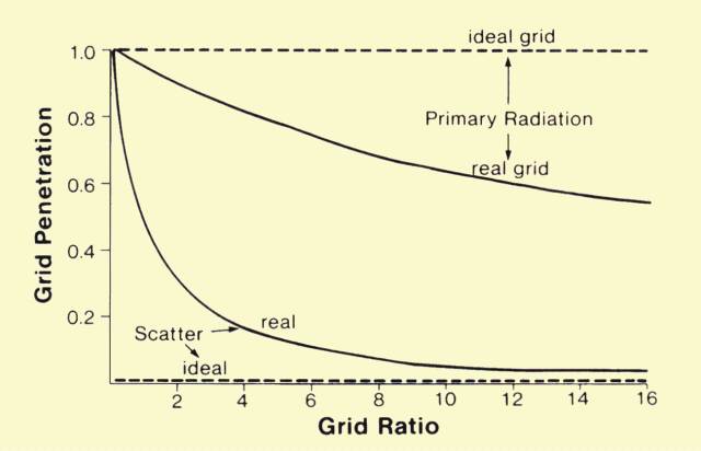 General Relationship between Radiation Penetration and Grid Ratio
Primary penetration does not change with the amount of scattered
radiation, but does change with grid ratio. On the other hand,
scattered-radiation penetration is strongly dependent on grid ratio and
the amount of scattered radiation in the beam. Because the typical grid
removes more scattered than primary radiation, total penetration
decreases as the scattered-radiation content of the beam increases. The
two major factors, therefore, that determine total grid penetration are
the grid ratio and the scatter factor, S.
It is common to express grid penetration in terms of the Bucky factor, named after Dr. Gustave Bucky, who constructed the first grid in 1913. The Bucky factor is the reciprocal of the total grid penetration, or
Bucky factor = 1
/ Grid penetration.
Grid penetration and Bucky factor values are shown below for various grid ratios and scatter factors.
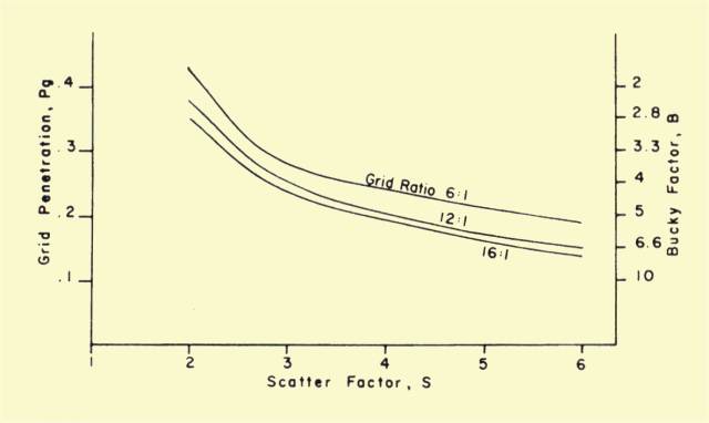 Grid Penetration and Bucky Factor Values
It should be recalled that, in most cases, there is a correlation between S and
KV. Since high
KV values are generally used for thick body sections, and both factors increase S, grid penetration appears to decrease as
KV increases. This is because scatter radiation content at the higher
KV
values is generally greater than for primary radiation.
The amount of radiation delivered to a patient's body must be increased to compensate for the radiation absorbed by the grid. Patient exposure is directly proportional to the Bucky factor. For example, if a grid with a Bucky factor of 3 is replaced by one with a Bucky factor of 6, the exposure to the patient must be doubled to compensate for the additional grid absorption. |
|
Scatter Penetration |
|
|
The relationship between the quantity of scattered radiation that passes through the grid and the grid ratio ca
 n
be visualized by referring to
the illustration shown here.. Consider the exposure that reaches a
point on the receptor located at the bottom of an interspace. Since no
radiation penetrates the lead strips, radiation can reach the
point on the receptor only from the directions indicated. The amount of
radiation reaching this point is generally proportional to the volume
of the patient's body in direct "view" from this point. As grid ratio is
increased, this volume becomes smaller, and the amount of radiation
reaching this point is reduced. In effect, with a high-ratio grid, each
point on the receptor surface is exposed to a smaller portion of the
patient's body, which is the source of scattered radiation. n
be visualized by referring to
the illustration shown here.. Consider the exposure that reaches a
point on the receptor located at the bottom of an interspace. Since no
radiation penetrates the lead strips, radiation can reach the
point on the receptor only from the directions indicated. The amount of
radiation reaching this point is generally proportional to the volume
of the patient's body in direct "view" from this point. As grid ratio is
increased, this volume becomes smaller, and the amount of radiation
reaching this point is reduced. In effect, with a high-ratio grid, each
point on the receptor surface is exposed to a smaller portion of the
patient's body, which is the source of scattered radiation.
Using basic geometrical relationships, the theoretical penetration of scattered radiation through grids of various ratios can be determined. This is shown graphically in the figure above titled, "General Relationship between Radiation Penetration and Grid Ratio." In actual usage, the relationship can differ from the one shown, especially for certain grid ratio-KV combinations. |
|
Primary Penetration |
|
|
Because of the presence of the lead strips, grids attenuate part
of the primary radiation. The penetration of primary radiation through
the grid is generally in the range of 0.6 to 0.7. This value depends on
grid design and is generally inversely related to grid ratio.
|
|
Contrast Improvement |
|
|
It has been shown that as the grid ratio is increased, a greater
proportion of the scattered radiation is removed from the beam. By using
the scattered-radiation penetration shown in
the figure above titled, "General Relationship between Radiation
Penetration and Grid Ratio," and an average primary penetration of
0.65, it is possible to calculate the expected contrast for various
combinations of grid ratio and scatter factors, S. Some values are shown
in
the figure below.
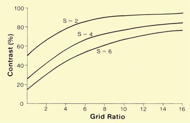 Relationship of Image Contrast to Scatter and Grid Ratio
For a grid ratio of 0, that is, no grid, the contrast percentage
is equal to 100 divided by S. As grid ratio is increased and scatter
penetration decreases, contrast improves. For relatively small amounts
of scattered radiation, that is, S = 2, a grid ratio of 8:1 restores the
contrast to 90%. The additional improvement in contrast with higher
grid ratios is relatively small. It should be noticed, however, that
even with high grid ratios, all contrast is not restored. When the
proportion of scattered radiation in the beam is higher, for example,
when S has a value of 6, the situation is significantly different. At
each grid ratio value, the contrast is much less than for lower scatter
factor values. Even with a high-ratio grid , such as 16:1, the contrast
is restored to only about 76%. This graph illustrates that contrast is
not only a function of grid ratio, but is also determined by the
quantity of scattered radiation in the beam, the value of S.
It might appear that the data in the figure above indicate that grids do not remove as much scattered radiation when the amount of scattered radiation in the beam is relatively large, such as for a value of S of 5 or 6. The relatively lower contrast obtained with large amounts of scattered radiation is because of the very low contrast values present without the grid. Actually, grids improve contrast by larger factors when the proportion of scattered radiation in the beam is higher. This can be illustrated by observing values of the contrast improvement factor, K, as shown in the figure below. The contrast improvement factor is the ratio of the contrast when a specific grid is used compared with the contrast without the grid. It is a function of the grid penetration characteristics and the amount of scattered radiation, S. 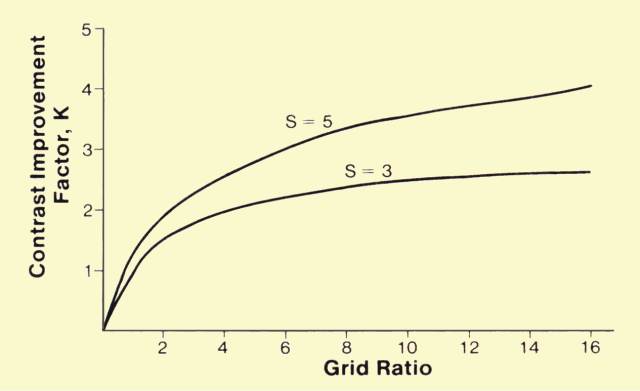 Relationship of Contrast Improvement Factor to Scatter Factor and Grid Ratio
The value of the contrast improvement factor, K, generally
increases both with grid ratio and with the quantity of scattered
radiation in the beam, S. Although it is true that grids improve
contrast by larger factors under conditions of high levels of scattered
radiation, one significant fact should not be overlooked: the total
restoration of contrast for a given grid is always less for the higher
values of scattered radiation. This becomes apparent by comparing the
value of the contrast improvement factor to the value of the contrast
reduction factor, which is equal to the value of S. This expresses the
ability of a grid under various scatter conditions to recover lost
contrast. For example, in
the figure above it is shown that when S is equal to 5 (contrast
reduced to one fifth) a 16:1-ratio grid produces a contrast improvement
factor of 4. The contrast recovery, K/S, is four fifths, or 80%.
However, at a lower level of scattered radiation, such as S = 3, the
same grid produces a contrast improvement factor of 2.7, which
represents a contrast recovery of 2.7/3, or 90%.
The relationship between the improvement in contrast and grid
ratio strongly depends on the proportion of scattered radiation in the
beam emerging from the patient's body. This, in turn, is a function of
patient thickness, field size, and
KV.
Under conditions that produce high scatter radiation values, a given
grid improves contrast by a greater factor, but cannot recover as much
contrast as is possible at lower scattered radiation levels.
|
|
Artifacts |
|
|
Since
the grid is physically located between the patient and the receptor,
there is always a possibility that it will interfere with the formation
of the image. This interference can be in the form of an image of the
grid strips (lines) on the film, or the abnormal attenuation of
radiation in certain portions of the field.
|
|
Grid Lines |
|
|
To some extent, the appearance of grid lines in the image depends
on the thickness of the strips and the interspaces. This is usually
specified in terms of the number of strips, or lines, per unit distance.
The spacing of lines in grids normally encountered ranges from
approximately 24 lines to 44 lines per centimeter (60 to 110 lines per
inch). The grid lines are generally less distracting for the higher
spacing densities.
A method frequently used to eliminate grid lines in the image is
to blur them by moving the grid during the exposure. The mechanism for
accomplishing this was first introduced by Dr. Hollis Potter, and a
moving grid system is often referred to as a Potter-Bucky diaphragm. In a
Potter-Bucky system the grid moves at right angles to the grid lines.
The speed at which the grid moves determines the shortest exposure time
that will not produce grid lines.
Grid motion during exposure also helps eliminate image patterns
created by the irregular spacing of grid strips. This type of
interference is generally less when grids with aluminum interspaces are
used.
|
|
Grid Cutoff |
|
|
The
basic function of a grid is to absorb radiation that is moving along a
path that is not aligned with the grid interspaces. It is desirable that
the primary radiation from the x-ray tube focal spot pass through the
grid with a minimum of absorption. Maximum grid penetration by primary
radiation can occur only if the x-ray tube focal spot is located at the
grid focal point. If these two points are not properly aligned, as shown
in
the figure below, the direction of the primary radiation might be
such that the radiation does not adequately penetrate certain sections
of the grid.
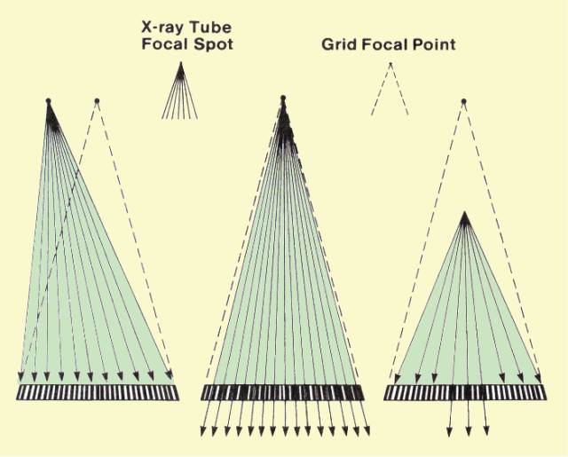 Two Forms of Grid Misalignment That Can Produce Cut-off Artifacts Misalignment of the x-ray tube focal spot with respect to the focal point of the grid can be either lateral or vertical, or a combination of both. Lateral misalignment causes the x-ray beam to be misaligned with all interspaces, and grid penetration is decreased over the entire beam area. The amount of penetration reduction is related to the amount of misalignment and the grid ratio. Alignment becomes more critical for higher ratio grids. That is, the loss of grid penetration because of a specific misalignment is much greater for a high-ratio grid.
Vertical misalignment does not alter penetration in the center of
the grid, but decreases penetration near the edges. The loss of
penetration is related to the degree of misalignment and the grid ratio.
The reduction in penetration for a given degree of misalignment
increases with grid ratio. Focused grids are labeled with either a focal
distance or a focal range, which should be carefully observed to
prevent this type of grid cutoff. Cutoff toward the edges of the image
area will also occur if a focused grid is turned upside down because the
primary radiation will be unable to penetrate except near the center.
This produces an artifact similar to vertical misalignment but usually
much more pronounced.
|
|
GRID SELECTION for CLINICAL APPLICATIONS |
|
|
A number of factors must be considered when selecting a grid for a
specific application. In most cases, a grid is selected that provides a
reasonable compromise between contrast improvement and patient
exposure, machine loading, and positioning.
The advantages of a 5:1-ratio grid are that it is easy to use and does not require critical positioning. Its use must be restricted, however, to situations in which the amount of scattered radiation is relatively small (thin body section, low KV) or in which maximum image contrast is not necessary. On the other hand, a 16:1-ratio grid produces high-contrast recovery but significantly increases patient exposure. With a high-ratio grid of this type, there is very little latitude in positioning. Many applications are best served by grid ratio values between these two extremes. Such grids generally represent compromises between image quality and the other factors discussed. Some grids have strips running at right angles to each other, generally designated crossed grids. This design generally increases contrast improvement but cannot be used in examinations in which the x-ray tube is tilted. In stationary grid applications in which lines in the image are undesirable, grids with a high spacing density (lines per centimeter) can be used. An increase in the spacing density generally requires a higher ratio grid to produce the same contrast improvement. |
|
|
|
|
No comments:
Post a Comment